(a) Introduction
This document establishes conventions for use during Oracle development efforts for logical and physical objects. It establishes diagramming conventions to be used with the various diagramming tools provided case tools such as Oracle Designer. These standards are based on the functionality available within Oracle Designer 6i but may be applicable to other CASE design tools.†
The contents of the document have been established with the help and input and work from a variety of sources.† It encompasses the best practices and most effective methods we have been able to gather over the past 15 years of Oracle software development.† Many experienced developers to consultants have worked on this document and have made it the great resource that it is today.† We thank each one of them for their contributions.
This document is best used as a starting point for the development team and amended as necessary to reflect the best practices and naming conventions adopted the organization or agency for whom the work is performed for or by.
(b) Objectives
The purpose of this document is to provide a common basis for analysis and development of business systems using a standard format for code, designs, and diagrams. The standards and conventions established by this document are intended to assist in the integration of methodologies and applications across all business areas within a given company. Standardization is critical to the successful achievement of quality in the system engineering process.
This document establishes standards for system development and sets naming conventions for logical and physical objects as well as for data and process elements.†† It is expected that the standards contained herein will continue to evolve to support the changing needs of the company or organization.
(c) Applicability†††††††††††
This document applies to all custom development efforts that will be developed using Oracle Designer or a suitable CASE tool with the target application platform based on PL/SQL 8.0 or greater and/or Forms 6i or greater.
(d) References
This document adopts selected standards that were developed by the Oracle Corporation.
(e) Access
This document can be accessed via the web or through various downloaded formats.
†
(f) Document Organization
This document is organized into seven distinct sections:
∑ Oracle Objects
∑ Strategy/Analysis
∑ Design
∑ Coding Standards
∑ Build
∑ Diagramming Conventions
∑ Appendices
The individual sections
contain any additional rules specific to an object and one or more examples to
illustrate usage.
(a) Length of Labels
ORACLE database object names are restricted to no more than thirty (30) characters and include entities, attributes, tables, columns, views, sequence generators, and domains.† However, some Designer utilities may add a suffix of 4 additional characters for example ď_JNLĒ.† For this reason, the recommended length is 26 characters. The wordsí Ďaliasí and Ďshort nameí are used to describe a codified label of two (2) to four (4) characters. The word Ďnameí will signify a descriptive label of three (3) to twenty-six (26) characters.† Names should be meaningful, and should accurately describe the object to which they are assigned.† Oracle Applicationsí data names for entity and attributes should be used if possible.† The consistent use of abbreviations and standard acronyms will assist in this endeavor.
(b) Acronyms/Abbreviations
Full words should always be used, unless an approved acronym can be substituted or an abbreviation is required for length considerations.†† In other words, always substitute an acronym if an appropriate one exists, and only abbreviate when necessary because of name length considerations.† (An acronym is a word formed from the initial letter or letters of each of the successive or major parts of a compound term.)
If name length considerations mandate abbreviation of words, begin the abbreviation process from the right. If the word has an approved abbreviation, substitute the abbreviation.† If, after all appropriate acronyms and abbreviations have been substituted, it is still necessary to reduce the length of a label, begin to abbreviate the last word in the label and continue to reduce one word at a time until the total length of the label is acceptable. Apply the following techniques, in the order given, to create a unique abbreviation of appropriate length.
∑ Remove internal vowels and final Ďeí.††
††††††† Example: country is abbreviated Ďcntryí, object is abbreviated Ďobjctí.
∑ Sequentially remove consonants beginning at the end of the word.
Example: address is abbreviated Ďaddrí, abbreviation is abbreviated Ďabbrí.†††††
An abbreviation should be no less than three and no more than five characters.† In some instances, an abbreviation of two (2) characters is allowable if the meaning of the abbreviation is clear and/or it is in common usage such as Ďozí, Ďftí, or Ďlbí.† If the qualifying word is four or fewer characters long, it should not be abbreviated.
Tables of standard abbreviations and acronyms are provided in Appendix A - Approved Abbreviations, Codes and Acronyms.
If further assistance is required, contact the Data Administrator to determine the acronym(s) or abbreviation(s) required. If you have created a new abbreviation using the rules above, contact your Data Architect to update the approved abbreviation, codes and acronyms list.
(c) Use of Significant Words
Use root words wherever possible.† Dropping the suffix (-age, -ence, -ance, -ing, -ant, -ity, -any, -ive, -ary, -ony, -aty, -ory, -ation, -ment, -ed, -tion) will generally leave the root word.†† Do this only if the remaining root word is meaningful as is.
Words such as who, what, when, or where are not allowed.
The use of articles and prepositions (such as the or of ), adjoining words or conjunctions (such as and or or), qualifying words such as new or old, and numbers should be on an exception basis.
(d) Use of Special Characters
Special characters, including brackets, quotation marks, question marks, and slashes are not permitted.† Dashes are allowed only in legitimately hyphenated words.
Underscores will not be used except where needed to separate words in physical implementation objects (like tables, columns, and modules). The Designer tool will insert underscores, when required, during transformation from logical to physical repository objects.†
Section 1.03 Strategy and Analysis
This section describes naming standards for objects that will be encountered or defined in the Strategy or Analysis phase of application development.
(a) Application Name
Application names should be representative of the Master Development Project it is associated with.† These names and divisions should apply to the highest levels of the organization.
Application names should have a maximum of 10 characters.
For example, valid application abbreviations might include:
1. LO††††††††††††††††††††††††††††††† Logistics
2. PM†††††††††††††††††††††††††††††† Product Marketing
3. ER††††††††††††††††††††††††††††††† Employee Relations
4. FN††††††††††††††††††††††††††††††† Financials
5. PR††††††††††††††††††††††††††††††† Production
6. AC†††††††††††††††††††††††††††††† Acquisitions
7. VP††††††††††††††††††††††††††††††† Vendor Packages
(b) Business Process
Business processes should be captured using the Process Modeler and the Function Hierarchy Diagrammer or an equivalent tool.
The first task is to establish all of the highest level Business Processes and enter them into the root process model.†† Standard industry descriptions should be used, and should continue to be used to identify business processes throughout the design.†
As additional process models are developed, they should be appended to the appropriate higher level process in the Enterprise Model.† These extensions of the Enterprise Model should not exceed two additional levels of business processes before functional decomposition begins.
Additional levels may be required for very complex models but in general should be avoided.
At the highest two levels of the enterprise, the business process labels have a single alpha character and should have already been established as described above.† All subsequent levels of business processes should be composed of three (3) alpha characters where the first of the three characters is the name of the level two parent.
Example:
Labels are automatically displayed in functional hierarchy diagrams in Designer to help identify processes and functions hierarchic relationships.
Refer to the illustrations in the handbook in Chapter 5 Business Processes & Functions.
(ii) Business Process short definition
The short definition of a business process is always a noun or nominative phrase.
Example 1:
Accounting and Fixed Assets are standard high level processes;
Accounts Payable, Accounts Receivable and General Ledger are processes which are functions of the higher level process, Accounting;
Asset Acquisition, Asset Capitalization, Asset Depreciation and Asset Retirement are processes, which are functions of the higher level process, Fixed Assets.
Example 2:
Planning, Customer Service and Marketing are standard high level processes;
Customer Account Maintenance and Collections are processes, which are functions of the higher level process, Customer Service.
(c) Business Functions
A business function is a named action performed by one or more business units as part of a business process.
All business function labels are limited to ten (10) characters.
Labels are a concatenation of the label from the parent business process, and from one (1) to seven (7) numeric characters. The digits, which identify the level of functional decomposition within the business process are positional and begin with one (1).† This scheme supports a maximum of seven (7) levels of functional decomposition of a business process.
The use of alpha characters in the positional parameters is optional and should be established by the project team at the onset of the project.††
Examples:
CAM1: Establish New Account
Where:
C = Customer Service (primary Business Process)
CAM1 = Establish New Account (First, First Level Function of the process CAM Account Maintenance)
CAM11: Conduct interview
††††††† Where:
C = Customer Service (primary Business Process)
CAM1 = Establish New Account (First, First Level Function in the process CAM Account Maintenance)
CAM11 = Conduct interview (First, Second Level Function in the process CAM1 Establish New Account)
CAM12: Record applicant data
††††††† Where:
C = Customer Service (primary Business Process)
CAM1 = Establish New Account† (First, First Level Function in the process CAM Account Maintenance)
CAM12 = Record applicant data (Second, Second Level Function in the process CAM1 Establish New Account)
(ii) Business Function Short Definition
Business Functions will have a short definition consisting of a verb and an object.† Always describe the function starting with a verb.† If you don't describe the function in this manner the name will be confused with a process. The short definition can consist of as few as two words, or it can be as long as a sentence.† It should clearly describe the complete activity carried out within the scope of that function.
Examples:† Establish New Account, Revise Existing Contract
(d) Common Functions
All Common Functions must include the master function label as part of the short definition.
Example:
Label: M11
Definition: Interview the customer (CAM11)
Where CAM11 is the master function ďConduct InterviewĒ.
(e) Data Stores
A datastore must have a name
and an id.
Datastore names describe the contents of the datastore and are restricted to thirty (30) characters.† Datastore IDs are limited to ten (10) characters.
Example:
CUSTOMER SERVICE
INFORMATION is the name
of a datastore that contains files, tables, paper forms, etc. related to
Customer Service.†
CSI is the ID for the datastore.
Data is the type for the datastore.
(f) Data Flows
Data flows do not have to be named.
Flow names describe the contents of the flow and are restricted to thirty (30) characters.
Data is the type for the data flow.
Example:
CUSTOMER ACCOUNT INFO is the name of a data flow that contains
information related to Customer Service Information datastore. †Customer Account Information may just be a
subset of the information defined by the datastore Customer Account
Information.
(g) Diagrams
In terms of diagram storage,
each CASE tool is slightly different.† In
this document we assume the use of Oracle Designer and therefore we assume the
use of the Designer repository.† Later
versions of Designer have a more complex paradigm for document storage and
applications.† We will focus on a simple
model for the purposes of this discussion.†
The names of all diagrams stored in the Designer repository should
therefore conform to these conventions.
Generally,
the name of a diagram should describe the functional area or business area view
of the Enterprise Model.
Diagram names should begin with the appropriate Diagram Type Code (shown in the table below) followed by a colon (:) or a dash (-) for file system methods, a blank space for repository diagrams, and a meaningful description of up to thirty-six (36) additional characters. This will allow you to distinguish the types of diagrams when viewing them from the Repository Object Navigator or in a file system.† If you are storing the diagrams in a file system it is recommended that you use initial caps in the file name following the dash without spaces followed by a lower case file extension if necessary.
|
Diagram Type |
†Tool Used to Generate Diagrams |
|
BP |
Business Process Modeller |
|
DD |
Data Diagrammer††††††† |
|
DF |
Data Flow Diagrammer |
|
ER |
Entity Relationship Diagrammer |
|
FH |
Functional Hierarchy Diagrammer |
|
MD |
Module Data Diagrammer |
|
MX |
Matrix Diagrammer††† |
The following sample diagram names illustrate usage of the convention.
††††††††††††††† BP: Accounting
††††††††††††††† ER: Customer Services Information
††††††††††††††† ER: Order Entry Information
††††††††††††††† FH:
††††††††††††††† BP-Accounting.dmi
††††††††††††††† ER-CustomerServicesInformation .dmi
††††††††††††††† ER-OrderEntryInformation .dmi
††††††††††††††† FH-EnterpriseModel.dmi
(h) Entities
Entity Names should be singular nouns or nominative phrases. They should be business-oriented, and will contain one blank space between each word.† Use single or multiple full-word descriptive names, but allow exceptions for approved acronyms and/or abbreviations (e.g., CUST or ADDR) when the name exceeds 24 characters.
∑ Entity names may not contain the names of physical constructs such as "file" or "table" as a qualifier.
Example: Use Customer not Customer File or Customer Table.
∑ Entities must not exceed 24 characters including spaces.† See the section on use of abbreviations if your entity name exceeds this limit.
Example: †CUSTOMER ADDRESS, ORDER HEADER, MAX UNIT OF MEASURE.
If you may be sharing entities from other vendor applications (e.g. Oracle Applications) with the same name as your entities, for example, CUSTOMER, you may want to prefix your entities with a two or three character application identifier. For example, if your application name is ANY COMPANY, then prefix your entities with ďACĒ (e.g.† AC_CUSTOMER).
It is recommended that all tables use a plural form of the entity name.
Thus the plural for each
entity must also be defined at the time an entity is named (since the DDT will
use this to create the table name).† Some
utilities impose a restriction on the length of the entity plural name. For example if you decide to create
journal tables using Designer, the tool will generate a three-character suffix
ď_JNĒ.
∑ Entity Plural must not exceed 26 characters including spaces.
An entity short name is composed of a distinct word or words (10 characters or less) or a concatenation of Entity word fragments.† Oracle Designer uses the short name in the generation of names for constraints, foreign keys, and sequences.† A user should be able to look at an entity short name and know to which entity it refers.† Since the entity short name may be used to create any migrated foreign-key column name, it is important that the short name indicate the entity from which it came.†† Use a standard abbreviation if one exists.† Short names should be a minimum of 2 characters and a maximum of 10.††
If an entity name consists of
one word, the short name should be the first
Example:† CUST is the short name for the entity CUSTOMER;
ADDR is the short name for the entity ADDRESS;
PN will be the short name automatically created for PHONE NUMBER.
OH will be the short name automatically created for ORDER HEADER.
Entity Short Name
|
Entity Name |
Entity Short Name |
|
PERSON |
PER |
|
PERSON ELIGIBILITY |
PE |
|
PERSON ENTRY |
PEREY (duplicate example) |
An intersection entity associates two different entities and resolves a many-to-many relationship.† It is named according to its business functionality.†
Example:
If entity one is named ORDER and entity two is named PRODUCT, an intersection entity may be created called ORDER ITEM.
If there are no business terms that will work, the name is simply formed from the names of the entities which are associated.
Example:
CUSTOMER ADDRESS describes the connection of the CUSTOMER and ADDRESS entities.
A validation entity is one that contains ďlookupĒ or code information. Validation entities should be suffixed with a blank space and the word "CODE" or ďTYPEĒ to distinguish them from other types of entities.
Example:
COUNTRY OF ORIGIN CODE
ORDER TYPE
CUSTOMER CODE
VEHICLE TYPE
†††††††††††††††††††††††††††††††††††††††††††††††††††††††††††††††
(i) Domains
An initial set of domains should be established and maintained for the enterprise by the Data Administrator (DA) and should reside in the Oracle Designer repository or a similar shared location for individual diagrammers to draw from.
Domain names may be up to (30) characters and should indicate the scope or contents of the domain. Do not place underscores between words in a domain name. If the name becomes too long, refer to the list of approved abbreviations and acronyms in the appendices of this document.
Examples:
†††††††††††††††††††††††††††††††††††† Address
†††††††††††††††††††††††††††††††††††† Amount
†††††††††††††††††††††††††††††††††††† Id
†††††††††††††††††††††††††††††††††††† Long Text (1000)
†††††††††††††††††††††††††††††††††††† Very Long Text (2000)
†††††††††††††††††††††††††††††††††††† Name
There are several things that domains should be commonly used to provide. They are:
∑ A list of values
∑ A range of values
∑ A specified data type and size
∑ Any combination of these.
The following properties are mandatory for all domains created for the enterprise:
∑ Name
∑ Attribute Format
∑ Column Datatype
∑ Maximum Length (both attribute and column)
∑ Comment (describes domain purpose, suggested uses, etc.).
Default initial values will also be specified, when appropriate.
Domains will also be used, as required, to provide lists of values (LOVís) when generating forms from Designer. For such a domain, known as a reference domain, the domain name will be the plural of the attribute referenced.
Example:†† STATES is the reference domain for the attribute STATE.†
In general, domains will be used only if the values are relatively static and encompass fifty (50) or fewer discrete values.†
Examples: STATES is an approved LOV domain because the values are static and limited.
AREA CODES is not an approved domain.† The values are not sufficiently limited.
The DA will construct additional domains as they become required and will be generated for the enterprise.†
(j) Attributes
An attribute is any detail, which serves to identify, qualify, quantify, classify, express the state of, or otherwise describe properties of an entity.†† Each occurrence of an attribute within an entity has one and only one value.† An attribute, or data element, is a characteristic of each occurrence of an entity.† Attribute definitions are written in clear, concise English and have sufficient detail to distinguish them from the other attributes concerning the same entity.† The definitions should be robust enough to accommodate an ever-changing environment.† Furthermore, the definitions should be easy to understand by those unfamiliar with the companyís business functions.
Attributes are classified in the repository by functionality and depicted on Entity Relationship Diagrams with the following symbols:
|
Symbol |
Description |
|
# |
Primary Unique Identifier (UID) |
|
* |
Mandatory Attribute† (may not be null) |
|
O |
Optional Attribute (may be null) |
Attribute names are derived from their definitions.† They should not be application specific so as to accommodate reuse across the enterprise.† All attribute names should comply with the following standards:
∑ Attribute names may be up to 30 characters long.
∑ Attributes can have multi-part names and should not have underscores between the words.
∑ Attribute names should be as descriptive as possible without being overly convoluted.
∑ They should be named using terms an end-user will recognize as much as possible.
∑ If necessary, abbreviations and acronyms may be used to meet length requirements.
∑
Attribute
names should be singular nouns.
∑
Proper
nouns are never used as attribute names.
∑
Attribute
names may include appropriate adjectives or clauses to better describe the
attribute.
∑
Attribute
names should uniquely identify the attribute to distinguish it from other
attributes within the entity.
∑
Attribute
names should begin with only alphabetic characters.
∑
Attribute
names should be written in capital letters.
∑
Attribute
names should not be ORACLE reserved words.
The possible components of an attribute name are:
∑ ModifiersóA modifier is a noun or adjective that further defines or identifies an attribute to make it unique within the entity.
∑ Class WordóThe class word describes what type of data composes the attribute.† It has the second-most significance to the user.
The composition of an attribute name is shown in below.
Composition of an Attribute Name
|
Modifier(s) |
Class Word |
|
0 + n (optional) |
1 (required) |
All attribute names are described within the context of the entity.† First, the data attribute should be classified according to the type of data the element represents; this is done using the list of class words.† Next, all modifiers should be derived using words from the attributeís definition.† Modifiers are added to the name to ensure uniqueness from the other attributes within the entity.†
An example of the attribute naming process is shown below.
Note:† A single class word may be all that is needed to make the attribute unique.† Thus, it is possible to have an attribute that is comprised of one class word (for example, CODE).
Examples of attribute names include the following:
∑ CODEóClass word only
∑ PARAGRAPH NUMBERóOne modifier and a class word
∑ BIRTH STATE CODEóModifier, modifier, and a class word
∑ Start Date-
∑ End Date
∑ Description
When naming an attribute that participates in the UID, use the entity name (if it is relatively short) or the entity short name plus one of the following words as a suffix:
ID††††††††† is used for a UID that contains a system-generated number and is used internally during processing to access or link data. The values are meaningful only as pointers or keys, and usually do not show on end user reports or screens. The domain for IDs is ĎUIDí.
NBR is used for a UID that contains a number by which the end user recognizes the entity. NUMBERs are displayed on reports or screens to provide information to an end user.† The number may be system generated but is usually determined by the user or has been provided from a legacy system. The domain for NUMBERs in a UID is ĎUIDí.
CODE is used for a UID that contains an alphanumeric value by which the end user recognizes the entity. CODEs are displayed on reports or screens to provide information to an end user.† The value of the code is usually representative of the entity it identifies.† The domain for CODEs is ĎCODEí.
TYPE is used for an attribute that contains an alphanumeric value to represent a categorization of an entity (i.e., a sub-type).† The domain for TYPEs is ĎTYPEí.
Examples:
CUSTOMER ID: If the entity CUSTOMER has a system generated internal use UID, the attribute will be designated CUSTOMER ID.
CUSTOMER NBR: If the entity CUSTOMER has a system generated or user generated UID which is significant to the end user, the attribute will be designated CUSTOMER NBR.
CUSTOMER CODE: If the entity CUSTOMER were identified by an alphanumeric UID (e.g., GRAZ1), it would be called CUSTOMER CODE.
CUSTOMER TYPE: Account management recognizes several categories for Customers, such as commercial or residential.† Each grouping is identified by an alphanumeric value called CUSTOMER TYPE.
Except for these specific rules, attribute names should be determined by the same rules used for data entities in Section Entities.
Audit capabilities are required in all systems developed for the enterprise. Every entity must contain the following four audit attributes except code and type entities:
CREATE BY
CREATE DT
UPDATE BY
UPDATE DT
These audit attributes are to be detailed in the logical models for any entity.† When tables and columns are later generated from entities and attributes, the Database Design Transformer will create the appropriate columns.
Whenever possible, each attribute should have a domain type. In some situations it is possible that an attribute may have unique characteristics that are not repeated elsewhere; in this case, use of a domain would be of little value.
If the domain associated with an attribute contains allowed values, the attribute name will be the same as the domain name, only singular.†
To ensure all attribute definitions are consistent, the following are standards used for defining groups of attributes.†
For a ďCODEĒ attribute, the definition should begin:† ďA #-character code indicatingÖĒ.
For a ďDATEĒ attribute, the definition should begin:† ďThe date on whichÖĒ.
For a ďNUMBERĒ attribute, the definition should begin:† ďThe #-digit number assigned toÖĒ.
Abbreviations and acronyms that comprise an attribute definition should be spelled out.
|
Attribute Name |
Attribute Definition |
|
SEX CODE |
|
|
ENTRY DATE |
Attribute Definition Standards provides examples of a CODE and DATE attribute description.
(k) Relationships
Relationships should be named so that the diagram can be easily read.† To read any relationship simply and definitively, the following syntax is used:
Each (and every) ENTITY-A {must be, may be} relationship-name {ONE AND
ONLY ONE ENTITY-B (singular), ONE OR MORE ENTITY-B plural}
Where ENTITY-A is the source entity of the relationship, ENTITY-B is the destination end of the relationship, and relationship-name is the name applied to the relationship in the direction the relationship is being read.† Note the following rules:
∑
The choice between must be and may be is
determined by the modality (optionality) of the relationship emanating from the
source entity.† A solid line represents must be (mandatory) and a dashed line represents may be (optional).
∑
The choice between ONE AND ONLY ONE ENTITY-B (singular) and ONE OR MORE ENTITY-B plural is
determined, respectively, by the absence or presence of the ďcrows feetĒ at the
ENTITY-B end. This is also known as the cardinality of the relationship.
Since relationships are always bi-directional, naming a relationship requires two relationship names be supplied.† Hence, the relationship must be readable using the above syntactic structure in both directions.
Examples:
Each (and every) PERSON may be located at ONE OR MORE ADDRESSES.
Each (and every) ADDRESS must be the location for ONE AND ONLY ONE PERSON.
Each (and every) DEPARTMENT may be responsible for ONE OR MORE EMPLOYEES.
Each (and every) EMPLOYEE must be assigned to ONE AND ONLY ONE DEPARTMENT.
Whenever multiple relationships are created into a single entity, from the same parent entity, the relationship labels must be unique to prevent duplicate index names from being created by the Database Transformer.† Otherwise, the indexes will not be generated during ďDDL GenerationĒ
Do not use weak relationship names, such as ďassociated withĒ, or ďrelated toĒ. Remember that relationships are documenting business rules and will be used to explain the model to end-users. Whenever possible, use business terminology. For example, the correct way to document a person and their address would be:
A PERSON maybe located at one or more ADDRESSes, not a PERSON maybe associated with one or more ADDRESSes.
This section describes naming standards for objects that will be encountered or defined in the Design phase of application development.
(a) Modules
(b) Scope
The names of all modules developed with and generated from Oracle Designer should conform to these conventions. This includes all menus, reports, screens, libraries, webserver modules, and Visual Basic programs. In addition, all SQL*Plus reports (where documented) should also conform to these conventions. Changes to these standards should be approved by the lead Application Architect or according to the development teamís decision maker or leader.
The following distinctions between modules developed for or associated with Legacy systems and Vendor-supplied software and those to be developed for new or replacement systems are recognized:
All new or replacement systems developed internally should be developed using the Designer tool set, or through an appropriate and approved CASE tool.† All modules whether custom designed or generated from the CASE tool (hereinafter referred to as Designer) should adhere to these standards.
Legacy modulesí names should not be changed.† After Legacy software is recovered into the Designer repository, any future modules created to augment the legacy system should conform to these standards.
Vendorís modulesí names should not be changed.†† If objects from a purchased package are recovered into the Designer repository, and any modules are generated in-house to use those vendor objects, the new modules should be developed according to this standard.
(c) Format
Module names should consist of:
∑ a two character prefix representing the application
∑ two characters representing the Functional Area within the application
∑ one character identifying the type of module
∑ a sequence number
The following table lists the
valid module identifiers for potential application development:
††††††††††††††††††††††††††††††††††††††††††
|
Application System |
Value |
|
Logistics |
LO |
|
Acquisitions |
AC |
|
Financials |
FN |
|
Product
Marketing |
PM |
|
Production |
PR |
|
Employee
Relations |
ER |
|
Multiple
Application Systems (common module) |
CM |
The third and fourth characters of the name indicate the Functional Area (within an Application System) for which the module is developed.
|
Functional Area |
Value |
|
Accounts
Payable |
AP |
|
Accounts
Receivable |
AR |
|
Collections |
CL |
|
Cost
Accounting |
CA |
|
Employee
Benefits |
BE |
|
General
Ledger |
GL |
|
Planning |
PL |
|
Order Entry |
OE |
|
Shared
Module(common modules) |
SH |
The fifth character of the name indicates the Type of the Module.
|
Type of Module |
Value |
|
Oracle
Forms |
F |
|
Oracle
Forms Ė Query Only |
Q |
|
Oracle
Reports |
R |
|
Oracle
WebServer |
W |
|
Menu |
M |
|
Developer
Library (pll) |
L |
|
Object
Library |
O |
|
Template
Form |
T |
|
Reference
Form |
R |
|
Visual
Basic |
B |
|
SQL*Plus
Report (doc only) |
P |
The last component of the module name, the sequence number, is simply three digits, which are incremented by 10.† The increment may be modified to five (5) if the number of modules per subsystem becomes extremely large.
Following are some example module names using this standard:
Examples:
Name: FNAPF010
Translation: Financials applications, Accounts Payable subsystem, Oracle Form
Name: ERBEF010
Translation: Employee Relations application, Employee Benefits subsystem, Oracle Form
Examples:
Name: FNAPR010
Translation: Financials applications, Accounts Payable subsystem, Oracle Report
Name: ERBER0010
Translation: Employee Relations application, Employee Benefits subsystem, Oracle Report
Examples:
Name: FNAPM010
Translation: Menu for the Financials applications, Accounts Payable subsystem
Name: ERBEM010
Translation: Menu for Employee Relations application, Employee Benefits subsystem
Examples:
Name: FNAPL010
Translation: Oracle Developer library for Financials applications, Accounts Payable subsystem
Name: ERSHL010
Translation: Oracle Developer library containing shared program units for the Employee Relations application
(d) Module Components
All Module Components (MC) must adhere to the following naming convention:
∑ The name must include the alias of the base table name upon which the module is based.
Example: INV is the MC name for a component based on the Invoices table
∑ If there will be multiple components within a module using the same base table, then the name will include an underscore followed by an abbreviation of the purpose.
Example: INV_QRY is the MC name for a second component based on the Invoices table that will be query only
(e) Reusable Module Components
All Reusable Module Components (RMC) must adhere to the following naming convention:
∑ The name must include the base table name and a prefix of R_
Example: R_Invoice
∑ If there will be multiple reusable components with different layout styles, then the name will include an underscore followed by one of these abbreviations:
ST = Spread table
OR = Overflow area right
WL = Wrap line
Example: R_Invoice_ST
∑ If the display characteristics specify a number of rows, the name will include an underscore followed by that number, otherwise the word ďMAXĒ will be included
Example: R_Invoice_ST_MAX or R_Invoice_ST_6
∑ If a RMC is ďquery onlyĒ then the name will include an underscore followed by the letter ďQĒ (_Q), if it allows insert then use ďIĒ, if update use U, if delete then D. If all of these are used then add nothing.
Examples: R_Invoice_ST_MAX_Q, R_Invoice_ST_MAX_QIU
∑ If there are multiple RMCs with the same base table and some contain all the possible enterable columns, these RMCís will include and underscore and the word ALL. If there is only one RMC for a base table, no notation is required.
Example: R_Invoice_ST_MAX_ALL
∑ If the RMC name becomes too long (over 20 characters), then use the table alias instead
Example: R_Invoice_line_items_ST_MAX_ALL becomes R_ILI_ST_MAX_ALL
∑ If the RMC is not based on a table (i.e., a control block) it should be named with the prefix CTL followed by a string that represents its basic functionality or usage.
Example: R_CTL_calc_totals
∑ If the RMC is based on a PL/SQL package then it should be named with PLSQL followed by the name of the package.
Example: R_PLSQL_MyPackage
(f) Module Component Elements
All Module Components Elements must adhere to the following naming conventions:
∑ Item groups may be named to represent a functional grouping of data. The name may be multiple words with no underscores between them.
Example: The item group encompasses columns that make up the information for a mailing address so the item group is named MAILING ADDRESS
∑ If the layout item group is a horizontal item group, the name should be prefixed with an ďHĒ. If it is a vertical item group, it should be prefixed with a ĎVí. (Additional prefixes may be developed to represent the additional functions for which item groups are used in reports generation.)
Example: H MAILING ADDRESS is a horizontal item group containing columns for a mailing address
∑ If the purpose of the item group is to enable the generation of a specific layout then the name should be LAYOUT #, where # represents an integer.
Example: V LAYOUT 1 is a vertical item group used specifically for layout generation
∑ If nested item groups are used to achieve a complex layout then the name of the nested item groups should be† NESTED LAYOUT #-#, where the first # represents the number associated with the parent layout group and the second # is a sequential integer within that group
Example: H NESTED LAYOUT 1-2 represents the 2nd nested item group within the item group named LAYOUT 1. It is a horizontal item group.
Example: V NESTED LAYOUT
∑ All unbound items should be prefixed with UB and an underscore followed by text that describes its function. Approved abbreviations and acronyms may be used as necessary.
Example: UB_TOTAL_PRICE is an unbound item that will contain the results of a calculation for total price
∑
All SQL Query sets should be named with the word
Example: UNOIN EMP is the name of the query set containing a reference to the EMPLOYEES base table usage
∑ Navigation action items should be named using a prefix of NA followed by the module component name followed by the target module component or module name with an underscore in between
Example: NA_CUST_FNAPF010 indicates a button to navigate from the CUST component in the current module to the module FNAPF010
∑ Custom action items should be named using the prefix CA followed by text that describes the function of the action item. Approved abbreviations and acronyms may be used as necessary.
Example: CA_CALC_TOTAL indicates a button that when pressed will cause a total to be calculated
∑ All code segments entered to implement custom application logic should be named using a text string that defines the purpose of the code. Approved abbreviations and acronyms may be used as necessary.
Example: Use parameter value when present
∑ Named routines should conform to the same standard set forth for PL/SQL procedures
∑ API Logic code segments should conform to the same standard set forth for Application Logic code segments
(g) Named Preference Sets
All preference sets should be named with one of the following prefixes that indicate at what level the preference set is intended to be used:
AP_ = Application
MD_ = Module
MC_ = Module Component
IG = Item Group
IT = Item
The rest of the preference set name should use abbreviations to describe the purpose of the set or the major preference settings for the preference set.†
For example, if you have an item group† (IG) preference set that sets the preferences to create a horizontal item group, allowing 2 items in each row, with a rectangle decoration and left justified title, you could name it ďIG_H_2_REC_LEFTĒ.††
If you have a preference set that is intended to be used for modules (MD) that consist of only tab canvases, you could name it ďMD_TAB_ONLYĒ.
(h) Tables
Table names should be the plural of the Entity names, with the spaces translated to underscores.† If the resulting name has more than 26 characters, see Appendix A and Appendix B for a list you can use to acceptably shorten the table name.
Table names will not be prefixed with an application abbreviation unless that prefix is inherited as part of the original entity name.
All tables must have an alias. The alias must conform to the same standard set forth for entity short names. If the table is based on an entity, then the alias should be the same as the entity short name.
To ensure that appropriate meta-data is included in the Oracle data dictionary, all tables must have a comment entered into Designer. This comment should describe the basic information stored in the table.
Scripts that create tables should accept a parameter for the tablespace name and include specific storage parameters.† Below is a sample create script for the TMP_GL_INTERFACE table:
†
† REM
=======================================================================
† REM =††† Copyright (C) 1996† <Company Name>
† REM =††††††††††††††††††††††† <Location>
† REM =††† All rights reserved
† REM
=======================================================================
† REM
† REM††† PROGRAM NAME:† TMP_GL_INTERFACE.sql
† REM††† PURPOSE††††
:† To create the custom
TMP_GL_INTERFACE table
† REM††† PARAMETERS†
:† Tablespace
† REM††† CALLED†††††
:
† REM††† CALLED BY††
:
† REM
† REM††† UPDATE HISTORY
† REM†††
† REM††† DATE††††††
NAME†††††††††††† DESCRIPTION
† REM††† ---------†
---------------†
-------------------------------------
† REM††† DD-MON-YY†
XXXXX††††††††††† INITIAL RELEASE
† REM
† REM
======================================================================
† CREATE TABLE
TMP_GL_INTERFACE
† ( PERIOD_NAME†††††††††††† VARCHAR2(15) NOT NULL,
††† SOURCE††††††††††††††††† VARCHAR2(15) NOT NULL,
††† ENTITY††††††††††††††††† VARCHAR2(02) NOT NULL,
††† DEPARTMENT††††††††††††† VARCHAR2(04) NOT NULL,
††† ACCOUNT†††††††††††††††† VARCHAR2(05) NOT NULL,
††† PRODUCT_LINE††††††††††† VARCHAR2(03) NOT NULL,
††† PRODUCT_TYPE††††††††††† VARCHAR2(03) NOT NULL,
††† DB_AMOUNT†††††††††††††† NUMBER†††††† NULL,
††† CR_AMOUNT†††††††††††††† NUMBER†††††† NULL,
††† REVERSE_FLAG †††††††††††VARCHAR2(01) NULL,
†††
REVERSE_PERIOD†††††††††
VARCHAR2(15) NULL,
†††
JE_SOURCE_NAME†††††††††
VARCHAR2(15) NULL,
†††
JE_CATEGORY_NAME†††††††
VARCHAR2(15) NULL,
††† PROCESS_FLAG††††††††††† VARCHAR2(01) NULL,
†††
LAST_UPDATED_BY†††††††† NUMBER,
† ††LAST_UPDATE_DATE††††††† DATE
† )
† PCTFREE 5
† PCTUSED 90
† TABLESPACE
&tblspace
† STORAGE
(INITIAL†††† 4096
†††††††††† NEXT††††††† 4096
††††††††††
MINEXTENTS† 1
††††††††††
MAXEXTENTS† 9999
†††††††††† PCTINCREASE
10);
†
† EXIT;
†††
Custom database objects might need to be accessible by other applications and users.† Grants and synonyms therefore must be created to allow these non-owners to access these objects..† The following is a sample create script to grant access to TMP_GL_INTERFACE table:
†
† REM
=======================================================================
† REM =††† Copyright (C) 1996† <Company Name>
† REM =††††††††††††††††††††††† <Location>
† REM =††† All rights reserved
† REM
=======================================================================
† REM
† REM††† PROGRAM NAME:† TMP_GL_INTERFACE_grant.sql
† REM††† PURPOSE††††
:† To grant access to
TMP_GL_INTERFACE table
† REM††† PARAMETERS†
:† Source user id,
† REM†††††††††††††††††† Source password,
† REM††††††† †††††††††††Destination user id
† REM††† CALLED†††††
:
† REM††† CALLED BY††
:
† REM
† REM††† UPDATE HISTORY
† REM†††
† REM††† DATE††††††
NAME†††††††††††† DESCRIPTION
† REM††† ---------†
---------------†
-------------------------------------
† REM††† DD-MON-YY†
XXXXX††††††††††† INITIAL RELEASE
† REM
† REM
======================================================================
† CONNECT
&source_user_id/&source_password
† GRANT ALL ON
TMP_GL_INTERFACE†† TO &dist_user_id
†
† CONNECT
&dist_user_id/&dist_password
† CREATE SYNONYM
TMP_GL_INTERFACE† FOR† &source_user_id. TMP_GL_INTERFACE;
† COMMIT;
† EXIT;
(a) Columns
A column name should be the same as the name of the attribute from which the column was mapped, with the spaces translated to underscores.†† The column name must not be a plural.† If the resulting name has more than 30 characters, use the approved acronyms and abbreviations in the appendices to shorten it.
If the column is not based on an attribute, then it should be named using the naming standard set forth for attributes with the exception that an underscore is used instead of a space between segments.
Column names will not be prefixed with the table short name.†† This can be controlled via a checkbox in the ĎSettingí dialog on the Database Design Transformer.
The Database Design Transformer will also prefix foreign key column names with the parent entityís short name by default unless the check box for this option is unchecked in the ĎSettingsí dialog.† Since the standard for naming primary UID attributes already includes using the entity name or entity short name, this option must be de-selected or the resulting foreign key column will be redundantly prefixed.
(b) Constraints
Constraint names will conform to the default Designer constraint naming conventions that are automatically created when using the Database Design Transformer. Any manually created constraints must conform to this standard.
The naming convention used by Designer is:
Primary key = <table alias>_PK††
Example: For the table CUSTOMER with the alias CUST the primary key will be:
CUST_PK
As for unique key constraints, the naming convention used by Designer is ambiguous. Use the following format:
Unique key = <table alias>_<col1>_<col2>_col3>_UK
where the col1,† col2, and col3 are optional and may be necessary when concatenated columns make up the unique key.
Example:† The table called ORDERS (ORD) has two columns that make up the unique identifier, FNAME and LNAME.† The unique key constraints will be named:
††††††††††††††† ORD_FNAME_LNAME_UK
Designer will generate one of two possible names depending on the number of relationships between two entities. Foreign key names are usually generated with the following algorithm:
Foreign key = <table alias of the target table>_<table alias of the originating key>_FK
Example:
ORDER _LINES (ORDLIN) >------------- ORDERS (ORD)
The foreign key constraint on ORDER_LINES will have the foreign key constraint name generated as ORDLIN_ORD_FK.
However, if a table has multiple foreign keys to one other single table, then the algorithm for the first foreign key constraint will be the same as above. However, the second constraint with be generated as follows:
Foreign key = <table alias of the target table>_<table alias of the originating key>_relationship name_FK
Where Ďrelationship nameí is the text associated with the relationship as depicted on the logical model.
Example:
††††††††††††††††††† shipped from
ORDERS >-----------------† LOCATIONS (LOC)
† (ORD) >-----------------† LOCATIONS†††
†††††††††††††††††† returned to
The foreign key constraints on ORDERS will have the foreign key constraint names generated as:
††††††††††††††††††††††††††††††††††††††††††††††††††††††††† ORD_LOC_FK
††††††††††††††††††††††††††††††††††††††††††††††††††††††††† ORD_LOC_RETURNED_TO_FK
For the sake of clarity, in this case the first FK constraint should be renamed to:
††††††††††††††††††††††††††††††††††††††††††††††††††††††††† ORD_LOC_SHIPPED_FROM_FK
This standard applies to table level check constraints as defined in the Design Editor.. The naming convention is:
Check constraint† = <table alias> _ what is being checked_CK
Where Ďwhat is being checkedí is either a column name or some abbreviated text to describe the condition being validated.
Example:† The table called Location_History (LOCHIST) has a check constraint to enforce an arc relationship.† The check constraint will be named:
††††††††††††††† LOCHIST_ ARC_ CK
Example:† The table called CP_X_Competitors (COMPET) has a check constraint on the column END_DATE to ensure it is greater than the start date.† The check constraint will be named:
††††††††††††††† COMPET_ END_DATE_CK
(c) Indexes
Designer does not create primary or unique key indexes.† Oracle7 and newer versions implicitly create the index when creating primary and unique key constraints in the database.†† Do not create primary key indexes in the repository as this will result in problems when running the DDL scripts generated from Designer.
The Oracle Designer naming convention for foreign key indexes is the foreign key constraint name with ď_IĒ appended at the end.†† Designer will automatically create foreign key indexes through the Database Design Transformer if it is specified in the run options.
Foreign key index = <foreign key constraint name>_I
Example: For the foreign key ORDLIN_ORD_FK, the resulting foreign key index name would be ORDLIN_ORD_FK_I
In the case where multiple foreign keys were generated, and one was subsequently changed, it will be necessary to manually modify the associated index name so that it matches the renamed constraint.
Example:
Designer created:
ORD_LOC_FK with index ORD_LOC_FK_I
You modified the constraint to:
ORD_LOC_SHIPPED_FROM_FK
So you will need to modify the index to be:
ORD_LOC_SHIPPED_FROM_FK_I
(d) Sequence Generators
In most cases sequence names should be created as follows:
Sequence = <table name>_SEQ
Where <table name> is the table for which the sequence will provide values to the primary key.†
Example: CUSTOMERS_SEQ
Additionally, sequences may need to reflect functionality because a single sequence may be used with multiple tables.† In this case, the standard is:
Sequence = <common
functionality>_SEQ
Example:
Three tables are generated from sub-types of the entity MODEL. They each represent a different type of model but to avoid potential key conflicts, the decision is to use one sequence for all the primary keys because they will all be mapped to a common cross-reference table. So the sequence name is MODEL_ID_SEQ since the sequence will generically represent a model identifier.
†
(e) Views
Materialized views should be named as follows
Materialized View name = <table name>_<criteria>_MV
All other views should be named as follows:
View name = <table name>_<criteria>_V
Where the table name is the name of the root (or Ďmasterí) table the view is based on.† The criteria qualifier is optional.
The maximum length for a view name should be 26. If the name of the view exceeds 26, then use the table alias, abbreviations and acronyms as needed. View names should be plural just like tables.
Example:
EMPLOYEES_V is a view on the EMPLOYEES table
The qualifier, if used, should give the end users a clear idea of the purpose and contents of the view. Use the criteria qualifier if
1. Using the table name alone is not unique
2. The view is based on a join of 2 or more tables
3. The view contains a where clause
4. The view is unusually complex.
5. The view is a summary.
Examples:
ACTIVE_CUSTOMERS_V provides information on only active CUSTOMERS.
EMPLOYEES_DEPARTMENTS_V is a view joining the EMPLOYEES table to the DEPARTMENTS table.
CUSTOMER_COMPLAINTS_V provides information about CUSTOMERS and their NOTES of type Ďcomplaintí.
TOTAL_CUSTOMER_SALES_V provides summary information on customer sales activity
(f) PL/SQL Packages
Packages should be named according to this standard:
Package name =<app>_<description >
Where <app> is the Designer application abbreviation and <description> is a one or two word explanation of the purpose. Select a description that will help simplify the naming of procedures stored within the package.
†Additional restrictions are:
1. Stored Package (i.e. Packages stored in the database) names should be 24 characters or less.
2. Library Packages, (i.e. Packages stored within a Oracle Developer library file) the package name should be unique within 27 characters.
Example: FNSH_CALC is a package containing various calculation routines for the financial application system
(g) PL/SQL Procedures
Packaged Procedures should be named using the following standard:
Procedure name = verb noun
The verb is the action and noun is a brief explanation of the purpose or output.† A procedure encapsulates an action and should therefore reflect that action it its name.† The name SET_GROSS_PROFIT is desirable over GROSS_PROFIT or GROSS_PROFIT_SET.
Do not reuse the application abbreviation or any part of the package name in the procedure name.
Example: †CALC_GROSS_PROFIT is a procedure to calculate the companyís gross profit.
Stand-alone procedures should be named using the following standard:
Procedure name = <app>_<verb noun` >
The verb is the action and noun is a brief explanation of the purpose or output.† The <app> is the application abbreviation of the owning Designer application.
Example: †ERSH_TERMINATE_EMPLOYEE is a stand-alone procedure for the Employee Relations applications that processes an employee termination.
(h) PL/SQL Functions
All PL/SQL functions should be sub-programs within a PL/SQL package.
All PL/SQL function names will conform to the following standard:
Function = <result set phrase>
The function name should reflect the result instead of the action as with a procedure.† ††Do not reuse the application abbreviation or any part of the package name in the procedure name.
Example:† HEADER_ID is a function that returns the header id column
Example: ZERO_TOT_UNIT_COUNT is a function that returns FALSE if the total unit count is greater than zero.
(i) Cursors
All cursors defined for PL/SQL programs will conform to the following standard:
Cursor =† c_<cursor name>
Where <cursor name> is a logical, meaningful, and concise name representing the function the cursor serves. †This applies when there is more than one cursor in the given program.† For simple, short procedures with only 1 cursor, it is acceptable to use the generic c1 variable instead.† It is also valid to use c1 or c[x] cursor names where the cursor is used for a simple fetch of a count or something similar and there are no other complex cursors used.† A complex cursor would be one used within a loop or other control structure.
Precede the <cursor name> with ďcĒ so that there are no conflicts with other PL/SQL program units (like functions).
The cursor variable should be aptly named within the constructs of a record set.† Where a single value is fetched this does not apply.† Where a simple cursor name is used, as in c1, then the cursor variable may be appropriately simplified as crec when a record set is the return type of the cursor.† When the cursor result is a single value, then the standard variable naming conventions apply instead.
If a cursor uses a where clause which includes and parameters for the function or procedure, those parameters should be passed into the cursor as a cursor parameter.
Example:† c_get_header_id is a cursor that selects the header id column into a variable called v_header_id.
Example: c_check_total_units is a cursor that checks to ensure the total count is greater than zero and is fetched into a Boolean variable v_zero_total_units.
Example: c_employee_data is a cursor that obtains an employee data rowset and is fetched into a cursor variable name v_employee_rec.
Example: c1 is a cursor that tests whether a record exists or not and is fetched into a cursor variable called crec.
Example: CURSOR c1 (c_header_id IN NUMBER) IS SELECT header_id FROM foo WHERE header_id = c_header_id) instead of CURSOR c1 IS SELECT header_id FROM foo WHERE header_id = p_header_id.† This assumes that p_header_id is a parameter to the procedure.
(j) PL/SQL Program Data
All arguments for PL/SQL packages and procedures will conform to the following standard:
Argument =† p_<argument name> for IN OUT or OUT only parameters or c<argument name> for IN only parameters
Where <argument name> is a logical, meaningful, and concise name representing the value that will be passed to the program unit. Where the argument will be used to hold the value of a column in a SQL statement, then <argument name> should be the same as the column name.
†Precede the <argument name> with ďp_Ē or ďcĒ (without an underscore) so that there are no conflicts with database object names or confusion as to which are PL/SQL arguments and which are database objects.† All arguments should be in lower case, excluding the prefix.
Example:† p_header_id or cheader_id
All PL/SQL program variables will conform to the following standard:
Variable = v_<variable name>
Where <variable name> should be a logical, meaningful, and concise name representing the value the variable will hold. Where the variable will be used to hold the value of a column in a SQL statement, then <variable name> should be the same as the column name.
†Precede the <variable name> with ďvĒ so that there are no conflicts with database object names or confusion as to which are PL/SQL variables and which are database objects.† All variables should be in lower case, including the prefix.
Example:† v_header_id
All PL/SQL program constants will conform to the following standard:
Constant = c_<constant name>
Where <constant name> should be a logical, meaningful, and concise name representing the use of the value the constant will hold. Where the constant will be used to hold a value to be assigned to a column in a SQL statement, then <constant name> should be the same as the column name.
†Precede the <constant name> with ďcĒ so that there are no conflicts with database object names or confusion as to which are PL/SQL constants and which are database objects or variables.† All constants should be in lower case, including the prefix.
Example:† c_header_id
All Oracle Forms global variables will conform to the following standard:
Variable = global.<variable name>
Where <variable name> should be a logical, meaningful, and concise name representing the value the variable will hold. Where the variable will be used to hold the value of a field in the data block, then <variable name> should be the same as the field name.
Global variables must always be referenced with Ď:GLOBAL.í preceding the variable name.†† Therefore, no additional prefix is required to distinguish global variables from local or standard variables.†† In order to avoid confusion, do not use the same name for both a global and a local variable.
Example: header_id (i.e., :global.header_id)
(k)
Database Triggers
All database trigger names and trigger logic definitions will conform to the following standard:
Trigger = <table alias>_ <when><type><level>_<further description>_TRG
Where† <table alias> is the alias of the table on which the trigger is based and <type> is the action performed by the trigger.† Valid types are: Insert, Update, and Delete. <Level> indicates if the trigger is fired for every row in the table or once for every DML executed. <When> refers to whether the trigger is executed before or after an insert, update, or delete. The rest of the name, which must end with an underscore and a ďTRGĒ, is to describe the purpose of the trigger.
Types should be abbreviated:
∑ Insert = I
∑ Update = U
∑ Delete = D
When should be abbreviated:
∑ Before = B
∑ After = A
Level should be abbreviated:
∑ Row = R
∑ Statement = S
Examples:
CPCAI_BUR_SAVE_LOC_TRG = A before update trigger to save previous location information for every row updated
CPCAI_AIUDS_CHG_STATUS_TRG = An after insert, update or delete trigger to change the status code in an audit table after each DML statement
Article II. Coding Standards
Developers should develop and test all programs using a development (DEV) database instance.† All source codes should be stored in their own home directory prior to moving them into source code control system.
Integration
Test Environment
Integration testing should be done in a test (TEST) database instance.† In practice, before a developer can move objects from DEV to TEST they should submit a migration request to the DBA who is responsible for the application system.
Name
Standards
The following standards should be followed for custom objects:
|
Object Type |
Name Format |
Explanation |
Comments |
|
SQL script |
DDDD.sql |
DDDD =
Description (up to 32 char) |
|
|
PL/SQL
Script |
DDDD.sql |
DDDD =
Description (up to 32 char) |
|
|
Stored
Procedure |
DDDD |
DDDD =
Description (up to 32 char) |
|
|
Stored
Function |
DDDD |
DDDD = Description
(up to 32 char) |
|
|
|
|
|
|
|
Procedure
Package |
DDDD_pkg |
PKG†† = Package |
|
|
|
|
|
|
|
Database
Trigger |
XXX_WIUDL_DDDD_TRG |
XXX = Base
table alias W: B =
Before †† A = After I = Insert U = Update D = Delete L: R = Row †† S = Statement DDD =
Description TRG = trigger |
|
|
Database
Trigger install script |
TABLE_TRG.sql |
TABLE =
Base table name TRG†† = Trigger |
|
|
Table |
DDDD |
DDDD =
Description (up †††††† to 32 char) |
|
|
View |
DDDD_V |
DDDD =
Description (up †††††† to 32 char) V††† = View |
|
|
Sequence |
DDDD_SEQ |
DDDD =
Description (up †††††† to 32 char) S††† = Sequence |
|
|
Index |
XXX_DDDD_Tn |
DDDD =
Description (up †††††† to 32 char) T: U =
Unique †† N = Non-Unique n††† = Sequence number |
|
|
Database
Object creation script |
OBJECT.sql |
OBJECT =
Name of the †††††††† database object |
|
(a) Remarks Block
All custom programs and scripts must contain the following remarks at the beginning of the source codes.
†REM
=======================================================================
†REM =†††
Copyright (C) YYYY† <Company Name>
†REM =††††††††††††††††††††††† <Location>
†REM =††††††††††††††††††††††† [for the <Client>]
†REM =†††
All rights reserved
†REM
=======================================================================
†REM
†REM†††
PROGRAM NAME:†† XXXXXXXX
†REM†††
PURPOSE ††††:
†REM†††
PARAMETERS† :
†REM†††
CALLED††††† :
†REM†††
CALLED BY†† :
†REM
†REM†††
UPDATE HISTORY
†REM†††
†REM†††
DATE†††††† NAME†††††††††††† DESCRIPTION
†REM†††
---------† ---------------† -------------------------------------
†REM†††
DD-MON-YY† XXXXX †††††††††††INITIAL RELEASE
†REM†††
†REM
======================================================================
††††††††††††
(b) PL/SQL Standards
∑ All the DML statements should be numbered. Before each DML statement, assign a unique number to a variable indicating statement_id.
Eg: v_statement_id := Ď1í;
††††† INSERT INTO ....
∑ All DML statements should have exception handlers. There should be WHEN OTHERS clause in the exception handler.
Eg:
BEGIN
†SELECT† .....
†INTO†††††† .....
†FROM†††† .....
†WHERE† .....
††††† EXCEPTION
†††††† WHEN NO_DATA_FOUND THEN
†††††††††††††††† ....
†††††††††††††††† ....
††††††† WHEN OTHERS THEN
†††††††††††††† DBMS_OUTPUT.PUT_LINE( v_statement_id || Ď:í || SQLERRM);
††††† END;
∑ Where possible, give the key values for which the exception has occurred.
†††††† Eg: (print v_appl_id)
†BEGIN
† v_statement_id :=
Ď2í;
† SELECT
APPLICATION_NAME
††† INTO V_APPL_NAME
††† FROM
FND_APPLICATION
†† WHERE
APPLICATION_ID = V_APPL_ID;
EXCEPTION
†† WHEN NO_DATA_FOUND
THEN
†††††††
DBMS_OUTPUT.PUT_LINE(v_statement_id || Ď:í ||Ď*** ERROR: Invalid
Application ID ***í† ||
TO_CHAR(V_APPL_ID));
END;
∑ All the variables used for assigning values fetched (either by fetch or select into) from database should have same characteristics as the source column.
∑ Ensure modularity by procedural abstraction. For eg:. In the main block of the program, have procedure/function calls if multiple statements need to be executed.
†††††† BEGIN
††††††† proc1(...);
††††††† proc2(...);
†††††† END;
∑ Indent the code from block statements and control statements by 3 char spaces.
∑ Parameter name should start with p_ (eg: p_et_of_books_id).
∑ Variable name should start with v_ (eg: v_set_of_books_id).
∑ Cursor name should start with cur_(eg: cur_gl_interface).
∑ Record names should start with r_ (eg: r_gl_interface). Also record name should include the cursor name.
∑ List all the declarations in alphabetical order.
∑ User defined exception names should start with e_(eg: e_invalid_item).
∑ Do not have more than one DML clause for each line. Indent the clauses to ensure that the list following DML clauses on each line starts in the same column.
∑ Use meaningful alias names for table names in the from clause rather than a, b, c, etc.
††††† Eg: SELECT jl.entered_dr
†††††††††††† FROM††† gl_je_lines jl,
††††††† ††††††††††††††††††††gl_je_headers jh,
††††††††††††††††††††††††††† gl_je_batches jb
(c) SQL*Plus Standards
Include the following statements in all the SQL*Plus files.
WHENEVER† OSERROR EXIT OSCODE
WHENEVER SQLERROR EXIT SQL.SQLCODE
For† SQL*Plus reports, include the following lines.
SET NEWPAGE 0
SET PAGESIZE 60
(d) Oracle Reports Standards
∑ Provide the documentation on the report in the comments at the report level.
∑ Adequately document the select statements by comments in the queries.
∑ Query names should start with Q_, followed by a meaningful name.
∑ The group names should start with G_ followed by a meaningful name.
∑ The place holder column names should start with H_, followed by a meaningful name.
∑ The compute column names should start with C_, followed by a meaningful name.
∑ The parameter names should start with P_, followed by a meaningful name.
∑ Summary column names should start with S_, followed by a meaningful name.
∑ Create default layout with appropriately named data model objects.† Oracle reports will name the layout objects as per the names of related objects in data model.
∑ Include all one time select statements(eg: selecting value_set_id for Account† or Set of Books Id) in report level triggers and place the result in place holder columns for use in queries rather than joining the tables in queries.
This section describes naming standards for objects that will be encountered or defined in the ďBuildĒ phase of application development.†† These objects are primarily database objects therefore the naming of these objects is developed with the cooperation of the lead Database Administrator (DBA). Any deviations from these standards should be approved by the responsible DBA.† Naming convention for tablespaces, database files, rollback segments, and other objects not listed should consult the appropriate DBA and reference OFA in the Oracle Administrators Guide.
(a) Snapshots
There are two kinds of snapshots that can be defined in Designer; simple and complex. Simple snapshots (ones accessing only one table) should be named in this way:
Snapshot name = <table name>_SS
Where ĎSSí represents Ďsnapshotí and the table name is the name of the table or view the snapshot is based on.
The maximum length for a snapshot name should be 26. If the name exceeds 26, then use the table alias, abbreviations and acronyms as needed. Snapshot names should be plural just like tables.
Example:
EMPLOYEES_SS is a snapshot of the EMPLOYEES table
Complex snapshots should be named in this way:
Snapshot name = <table name>_<criteria>_SS
The qualifier, if used, should give the end users a clear idea of the purpose and contents of the snapshot. Use the criteria qualifier if
1. Using the table name alone is not unique
2. The snapshot is based on a join of 2 or more tables
3. The snapshot contains a where clause
4. The snapshot is unusually complex.
5. The snapshot is a summary
Examples:
ACTIVE_CUSTOMERS_SS provides information on only active CUSTOMERS.
EMPLOYEES_DEPARTMENTS_SS is a snapshot joining the EMPLOYEES tables and the DEPARTMENTS table.
CUSTOMER_COMPLAINTS_SS provides information about CUSTOMERS and their NOTES of type Ďcomplaintí.
TOTAL_CUSTOMER_SALES_SS provides summary information on customer sales activity.
(b) Users
ORACLE usernames will follow a Windows NT user naming convention as defined by the Network Administration Guidelines available from Microsoft.† In the absence of these naming rules the names should consist of the first letter of the users name followed by the first 7 digits of the userís last name.
Example:† John Doe would have a username of ďjdoeĒ.
(c) Roles
Application specific roles should be named in this manner:†††††††††††††††††††††††††††††
Role = <Application abbreviation>_<Access level>
The access levels should be determined by the Application Administrator.
Examples of access levels might be ADMIN, USER, and REPORT. So examples of role names might be:
†††††††††††††††††††††††††††††††††††† PM_ADMIN
†††††††††††††††††††††††††††††††††††† PM_USER
†††††††††††††††††††††††††††††††††††† ER_REPORT
†††††††††††††††††††††††††††††††††††† AC_USER
(d) Profile
Profile names should describe the interaction of the ORACLE user with the database. The DBA and the Application Administrator should determine profile definitions together.
Some recommended profile names are:
∑ USER --† Profile for end users.† May be broken into multiple profiles if application warrants different resource limits for different types of users.
∑ SUPPORT --† Profile for developers supporting the application.
∑ DBA--† Profile for DBAs.
If the profile is application specific, then it should be prefixed with the application abbreviation.
Example: FN_USER
(e) Synonyms
The naming convention for synonyms is:
Synonym name = table or view name
Synonyms, whether public or private, should always match the underlying object that the synonym is referencing.†
(f) Control File
The convention for a control file name is:
Control file = CTL<n><SID>.ora
Where <n> is an integer, starting from 1 and <SID> is the database instance name.
Examples:
†††††††††††††††††††††††††††††††††††† CTL1ORCL.ORA
†††††††††††††††††††††††††††††††††††† CTL2ORCL.ORA
(g) Database Links
A database link should be the same fully qualified service name as the name of the remote database to which it points. The naming convention for a database link is:
Link = <remote database>
Where:
∑ <remote database> is the name of the remote database
∑ Service name is the fully qualified internal service name which is typically in the format <SID>.<DOMAIN>
Example: TEST.WORLD,† DEV.MICRODEVELOPER.COM,† or PROD.MDI.ORG.
(h) Schema
In Oracle Designer a schema is represented as a set of objects owned by a user within a database. As such no additional naming convention is required.
(a) GENERAL
This section of the standards document specifies standard practices for elements and characteristics of Diagramming.† By implementing consistent diagramming practices confusion will be minimized when interpreting diagrams and attempting to understand business rules.
The intent of this section is to establish Diagramming standards and guidelines that will accomplish the following:
∑ Increase consistency
∑ Improve readability
∑ Improve pattern recognition.
(iii) Applicability†††††††††††††††††††††††††††††††††††††††††††††††††††††††††††††
This document applies to all Custom development.
Some layout methodologies presented here are based on information from the Oracle book CASE*Method Entity Relationship Modeling by Richard Barker.
(v) †Document Organization††††††††††††††††††††††††††††††††††††††
This document is organized into six distinct sections:
∑ Process Model Diagrams
∑ Function Hierarchy Diagrams
∑ Entity Relationship Diagrams
∑ Data Flow Diagrams
∑ Matrix Diagrams
(b) Business Process Model (BPM) Diagrams
These guidelines should be implemented when creating BPM Diagrams via the Oracle Designer Business Process Modeler Diagrammer.
Rather then creating one large business process diagram, create many sub-diagrams.† This will eliminate the need to maintain one large diagram that will over time become unreadable and unmanageable.† Also, each process step of a business process diagram will appear as a function on a function hierarchy diagram.
Do not crowd many processes onto a single business process diagram.† In general, one diagram should contain no more than six to nine process steps.
If a single diagram contains more than nine process steps, consider drilling down on one of the more complex process steps into a new diagram.
Under File-> Summary Information, check the following to be displayed:
∑ Title
∑ Created
∑ Last Modified
∑ Author
∑ Application.
The legend must appear under and to the right of the Unspecified business unit.
While the diagram name may be somewhat cryptic, the diagram title should be indicative of the business area being modeled and be understandable by business users.
Example:†
Diagram Name = INTERVIEW APPLICANTS
Title = Interview Applicants Process
In this section, please refer to the example diagram; Figure BPM-1
Example of correct use of standards.
Following are the guidelines to be used for determining the layout of a BPM diagram:
1) Diagrams should include:
∑ Major process steps (i.e., no functions)
∑ Flows (i.e., data, material or temporal)
∑ Flow names
∑ Process labels
∑ Triggers and outcomes
∑ Stores (data and material)
2) Process Step Placement
∑ Place process steps in the business unitís swim lane that performs it.
∑ When possible, place process steps to the right of a dependent process step rather than under it. This will reduce the swim lane height.
∑ Place process steps that are associated with a trigger one extra grid-snap to the right of the business unit. This will make the printout more readable.
∑ Before creating a new process step, always use the Edit->Include facility first to prevent duplicate processes.
3) Drawing Flows
∑ Face arrowheads to the right if at all possible.
∑ Avoid line crossings if at all possible.
∑ Before creating a new flow, always use the Edit->Include facility first to prevent creation of duplicate flows.
4) Flow name placement
∑ When flow names are used, place flow names in the middle of the flow.
5) Label placement
Place the label of the process above and to the left of the process step using this method:
1. Copy label to the annotation text field, set annotation type to 'TEXT' in multimedia tab.
2. Check Display Annotation in Options->Custimize->Graghics menu item.
6) Material Store placement
∑ Before creating a new material store, always use the Edit->Include facility first to prevent creation of duplicate material stores.
∑ Place material stores in the Business Units swim lane to show that they are responsible for the material.
7) Data Store placement
∑ Before creating a new datastore, always use the Edit->Include facility first to prevent creation of duplicate datastores.
∑ Place datastores in the Unspecified swim lane.
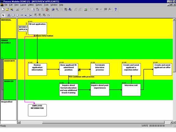
Figure BPM-1 Example of correct use of standards
Consolidate Diagrams frequently using Edit->Requery
In general, it is a good
practice to consolidate a diagram each time you open it to ensure that you are
working with current information. At a minimum, diagrams should be consolidated
when there is a change to the Designer Repository relative to business
functions, flows, stores, events (triggers) and business units. If you wish to keep historical views of
diagrams, save them under another name and do not consolidate them.
If a diagram is no longer needed, delete it from the Repository.
Use color coding or shading to distinguish the following:
∑ Process steps that are drilled down (open down) into sub-diagrams.
∑ Different type of flows (Data flows from material flows)
∑ Alternating business units and/or swim lanes
Do not use colors on the Unspecified business unit or its swim lane.
Use annotation in the form of notes or graphics to facilitate communication.
Set the specific type for all objects in the BPM whenever the type is known.
Display Diagrams in the following modes:
∑ Symbol Mode: Use Symbol mode for simple diagramming. This mode is appropriate for presentations to the non-technical business community.
∑ Enhanced Symbol Mode: Use Enhanced Symbol mode for flowcharting. This mode is appropriate for presentations to a more technical audience.
∑ Iconic Mode: Use Iconic mode to display associated icons for process steps, stores, and flows. This mode is appropriate for upper management and end-user presentations.
The BPM Diagrammer in Designer has a number of other options that can be used to enhance the presentation of a diagram. Below are some additional recommendations on the use of these features.
1) Images
Use images only if it facilitates communication.
2) Video
Use video clips only when it facilitates communication.
3) Sound
Use sound (digital recordings) only when it facilitates communication.
4) Animation
Use animation only when it facilitates communication.
(c) Function Hierarchy Diagrams (FHD)
These guidelines should be implemented when creating Function Hierarchy Diagrams via the Oracle Designer Function Hierarchy Diagrammer.
Rather then creating just one function hierarchy diagram, create many sub-diagrams.
∑ Create one diagram that will function as a view of the entire enterprise.
∑ Create a diagram for each of the major processes that are sub-functions of the root function.
Do not crowd many processes onto a single function hierarchy diagram.† In general, one diagram should contain no more than twenty functions.
If a single diagram contains more than twenty functions, consider drilling down on one of the more complex process steps into a new diagram.
Under File-> Summary Information, check the following to be displayed:
∑ Diagram
∑ Title
∑ Created
∑ Last Modified
∑ Author
∑ Application System
Display the legend in the upper left-hand corner of the diagram.
While the diagram name should be the same as the context function label, the diagram title should be indicative of the functional area being modeled and be understandable by business users.
Example:†
Diagram Name = ANY COMPANY
Title = "Any
Company"
This section lists some layout conventions that are helpful when creating diagrams. These conventions aid in making the diagrams easier for you to print and the business community to understand. The three layout styles are shown in figures FHD-1 through FHD-3.
Horizontal Layout is the default layout. This style shows each level of the hierarchy in a horizontal row.
Vertical Layout displays each level of the hierarchy in a vertical line, with each level indented slightly to the right of the one above it.
Hybrid Layout is a combination of vertical and horizontal layouts that shows parent functions in a horizontal layout and elementary (childless) functions in a vertical layout. This style is the best of the three options for reading and printing multilevel hierarchies.
In most cases, use the hybrid option as it uses the diagram space most efficiently. But this is really most dependent on how deep your function model is. If it is shallow and wide, often the horizontal layout will also look good. In general the vertical style should be avoided unless the model (or model segment) is very small.
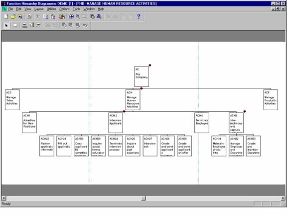
Figure FHD-1 Example FHD displayed in horizontal layout style
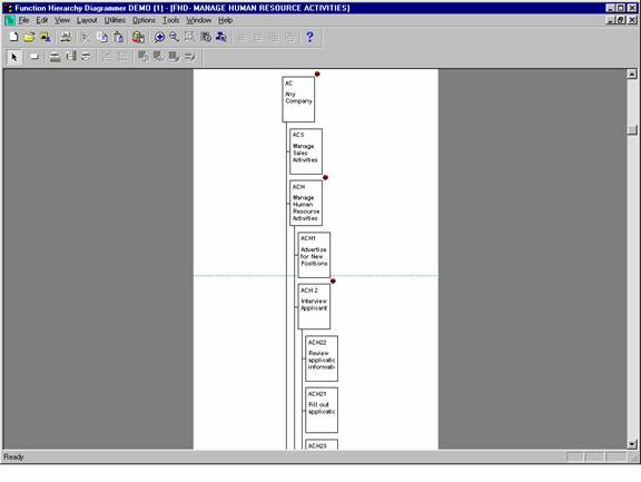
Figure FHD-2 Example FHD displayed in vertical layout style
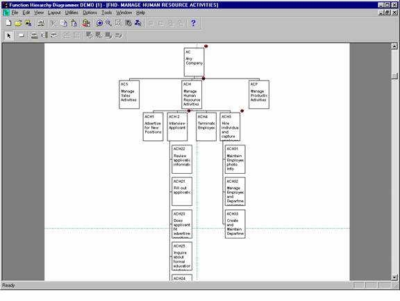
Figure FHD-3 Example FHD displayed in hybrid layout style
Consolidate Diagrams frequently using Edit->Requery
In general, it is a good
practice to consolidate a diagram each time you open it to ensure that you only
work with current information. At a minimum, diagrams should be consolidated
when there is a change to the Designer Repository relative to business
functions. If you wish to keep
historical views of diagrams, save them under another name and do not consolidate
them.
If a diagram is no longer needed, delete it from the Repository.
Use color coding or shading to distinguish the following:
∑ Elementary functions, functions that have been decomposed to their lowest level
∑ External functions, functions that are performed by external organizations but may have an effect on our organizations processes
∑
Functions that are the basis of other diagrams
(i.e., indicate the ability to open down)
(d) Entity Relationship Diagrams (ERD)
These guidelines should be implemented when creating ER Diagrams via the Oracle Designer Entity Relationship Diagrammer.
Rather than creating one large diagram, create many smaller diagrams.† This will eliminate the need to maintain one large diagram that will over time become unreadable, unmanageable, and overwhelming to non-technical users.† If you need to answer questions such as, what entities are related to other entities, use the Repository Object Navigator or the Entity Definition report. Do not rely on one large diagram.
Each diagram should correspond to a logical section of the overall business model. They could represent a specific business area or logical data view (In data warehousing terms these would be subject areas. For example; If you have a high level function called ďCapture Customer InformationĒ, create a diagram that will depict the data needed to support that business function.
Do not include entities that are not needed to support that high level function. The entity CONTRACT should appear on a diagram called ďCustomer ContractĒ along with all the other entities to support the creation and administration of a Contract, but it may not be needed on a diagram showing customer invoicing.
Do not crowd many entities onto a single diagram.† In general, one diagram should contain no more than 15 to 20 entities.
If a single diagram contains more than 15 entities, consider a logical refinement (e.g., the CUSTOMER INFO diagram would be subdivided into two diagrams: CUSTOMER INFO1 and CUSTOMER INFO2).
(iv) Display a Legend on the Diagram
Under File-> Summary Information, check the following to be displayed Diagram, Title, Created, Last Modified, Author and Application.
While the diagram name may be somewhat cryptic, the diagram title should be indicative of the business area being modeled and be understandable by business users.
Example:†
Diagram Name = ERD-CUST INFO
Title = Customer Definition Information.
In this section, please refer to the example diagram; Figure ERD-2 Example
of correct use of standards.
Following are the guidelines for to be used for determining the layout of an ER diagram:
1) Entity Placement
∑ Place fundamental entities to the right or bottom of the diagram.
∑ Size entities to reduce clutter and provide clear paths for relationships.
∑ Before creating a new entity, always use the Edit->Include facility first to prevent creating duplicate entities and relationships.
2) Drawing Relationships
∑ Face crowís feet to the left (West) or up (North).
∑ Avoid line crossings if at all possible.
∑ Keep relationship lines horizontal or vertical; do not angle them.
∑ Minimize the use of bent lines (straight lines are preferred).
3) Relationship name placement
Place relationship names in a clockwise pattern.
Tip: In
release 2.1.2, if you select a relationship and click on Autolayout, it will
place the relationship name in the pattern mentioned above.
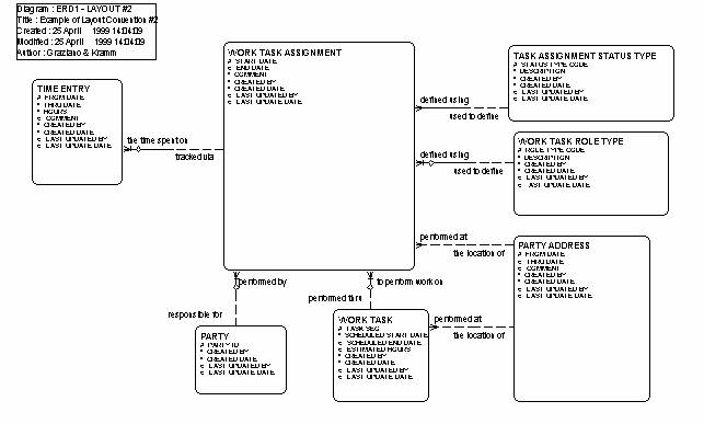
Figure ERD-2 Example of correct use of standards
Consolidate Diagrams frequently using Edit ->Requery.
In general, it is a good
practice to consolidate a diagram each time you open it to ensure that you work
only with current information. At a minimum, diagrams should be consolidated
when there is a change to the Designer Repository relative to entities or
relationships. If you wish to keep
historical views of diagrams, save them under another name and do not
consolidate them.
If a diagram is no longer needed, delete it from the Repository.
When drawing relationships to a sub-type entity, ensure that the line(s) between the sub-type and other entities are clearly connected to the sub-type and not its super-type.
Uses of sub-types imply that they will have attributes that are specific to them. If this is not the case, do not use sub-type constructs where simple examples will do. Instead, include examples as text on the drawing, where clarification is necessary.
Use color coding or shading to distinguish the following:
∑ Entities shared from other applications
∑ Entities that appear on more than one diagram
∑ Code type entities
∑ Subject area groupings
1) Strategy phase diagrams should include:
∑ Fundamental and transaction entities (i.e., no codes)
∑ Relationship lines
∑ Relationship names
2) Strategy phase diagrams may also include (where defined):
∑ Primary UID attributes
∑ Primary UID relationship indicators
3) Analysis phase diagrams should include (where they exist):
∑ All entities including code types and intersection entities
∑ All attributes
∑ All relationships
∑ Relationship names
∑ Primary UID relationship indicators
∑ Relationship transferability indicators
∑ Hidden arcs
(e) Server Model Diagrams
These guidelines should be implemented when creating SM Diagrams via the Oracle Designer Design Editor.
Rather than creating one large diagram, create many smaller diagrams.† This will eliminate the need to maintain one large diagram that will over time become unreadable, unmanageable, and overwhelming to non-technical users. If you need to answer questions such as, what tables have foreign keys to other tables, use the Design Editor (usages nodes) or the Table Definition report. Do not rely on one large diagram.
Each diagram should correspond to a logical section of the overall business model. They could represent a specific business area or logical data view. (In data warehousing terms these would be subject areas.) For example; If you have a high level function called ďCapture Customer InformationĒ, create a diagram that will depict the data structures needed to support that business function.
Do not include entities that are not needed to support that high level function. The table CONTRACTS should appear on a diagram called ďCustomer ContractĒ along with all the other tables and views to support the creation and administration of a Contract, but it may not be needed on a diagram showing customer invoicing.
Do not crowd many objects onto a single diagram.† In general, one diagram should contain no more than 15 to 20 tables of views.
If a single diagram contains more than 15 objects, consider a logical refinement (e.g., the CUSTOMER INFO diagram would be subdivided into two diagrams: CUSTOMER INFO1 and CUSTOMER INFO2).
Under File-> Summary Information, check the following to be displayed Diagram, Title, Created, Last Modified, Author and Application.
While the diagram name may be somewhat cryptic, the diagram title should be indicative of the business area being modeled and be understandable by business users.
Example:†
Diagram Name = SMD-CUST INFO
Title = Detailed Customer Data.
In this section, please refer to the example diagram; Figure SMD-2
Example of correct use of standards.
Following are the guidelines for to be used for determining the layout of a SM diagram:
1) Object Placement
∑ Place fundamental objects to the right of the diagram.
∑ Size objects so all columns can be seen and provide clear paths for foreign keys.
∑ Always use the Edit->Include facility first to prevent creation of duplicate objects and constraints.
2) Drawing Foreign Key Constraints
∑ Face crowís feet to the left (West) or up (North).
∑ Avoid line crossings if at all possible.
∑ Keep lines horizontal or vertical; do not angle them.
∑ Minimize the use of bent lines (straight lines are preferred).
3) Constraint name placement
Do not display foreign key constraint names.
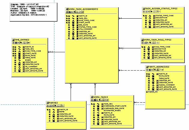
Figure SMD-2 Example of correct use of standards
There is no option to consolidate SM Diagrams. They are automatically consolidated upon opening.
If you wish to keep
historical views of diagrams, you must print them on paper (before a change
occurs) as there is no way to open one without seeing the underlying repository
changes.
If a diagram is no longer needed, delete it from the Repository.
Use color coding or shading to distinguish the following:
∑ Tables
∑ Views
∑ Snapshots
∑ Clusters
∑ Objects shared from other applications
∑ Objects that appear on more than one diagram
∑ Code type tables or views
∑ Subject area groupings
Each Server Model diagram created for a logical area should include (where they exist):
∑ All tables and views within that logical area
∑ All columns
∑ All foreign key constraints
∑ All column detail indicators
|
ABBREVIATION |
FULL
WORD |
|
ABBR |
ABBREVIATION |
|
ADDR |
ADDRESS |
|
ADMIN |
ADMINSTRATIVE |
|
ALT |
ALTERNATIVE |
|
ALTRTN |
ALTERATIONS |
|
AMT |
AMOUNT |
|
APP |
APPROVE |
|
APPL |
APPLICATION |
|
APPL |
APPLICATION |
|
ASGN |
ASSIGN |
|
AVG |
AVERAGE |
|
AWD |
AWARD |
|
BAL |
BALANCE |
|
BLK |
BLOCK |
|
BTN |
BUTTON |
|
BUF |
BUFFER |
|
BUS |
BUSINESS |
|
CALC |
CALCULATED |
|
CAN |
COMMON ACCOUNTING NUMBER |
|
CAT |
CATEGORY |
|
CB |
CHECKBOX |
|
CD |
CODE |
|
CERT |
CERTIFICATION |
|
CMT |
COMMENT |
|
CMTE |
COMMITTEE |
|
CNT |
COUNT |
|
CNV |
CANVAS |
|
COB |
COUNTRY OF BIRTH |
|
COMP |
COMPLETE |
|
COORD |
COORDINATE |
|
CR |
CREDIT |
|
CUM |
CUMULATIVE |
|
CUR |
CURSOR |
|
DEG |
DEGREE |
|
|
DELETE |
|
DEMO |
DEMONSTRATION |
|
DEPT |
DEPARTMENT |
|
DESCR |
DESCRIPTION |
|
DISP |
DISPOSITION |
|
DOC |
DOCUMENT |
|
DT |
DATE |
|
EDU |
EDUCATION |
|
EIN |
EMPLOYEE IDENTIFICATION NUMBER |
|
ELG |
ELIGIBILITY |
|
ELM |
ELEMENTARY |
|
EMPL |
EMPLOYEE |
|
EST |
ESTIMATE |
|
ESTAB |
ESTABLISHED |
|
EXC |
EXCEED |
|
EXP |
EXPENSE |
|
EXPIR |
EXPIRED |
|
FED |
FEDERAL |
|
FIN |
FINANCIAL |
|
FK |
FOREIGN KEY |
|
FNAME |
FIRST NAME |
|
FUN |
FUNCTION |
|
FY |
FYSCAL YEAR |
|
G |
GLOBAL |
|
GOVT |
GOVERNMENT |
|
I |
NDEX |
|
ID |
IDENTIFICATION |
|
IDX |
INDEX |
|
|
INDICATOR |
|
INFO |
INFORMATION |
|
INIT |
INITIAL |
|
INS |
INSERT |
|
INSTN |
INSTITUTION |
|
INSTR |
INSTRUCTOR |
|
INSUR |
INSURANCE |
|
ISS |
ISSUE |
|
LAB |
LABORATORY |
|
LIB |
LIBRARY |
|
LNAME |
LAST NAME |
|
LOV |
LIST OF VALUES |
|
MASK |
MASK |
|
MED |
MEDICAL |
|
MI |
MIDDLE INITIAL |
|
MISC |
MISCELLANEOUS |
|
MNAME |
MIDDLE NAME |
|
MOD |
MODIFICATION |
|
NAME |
NAME |
|
NBR |
NUMBER |
|
NOTE |
NOTE |
|
OG |
OBJECT GROUP |
|
ORG |
ORGANIZATION |
|
OTH |
OTHER |
|
P |
PARAMETER |
|
PA |
PROGRAM |
|
PC |
PROPERTY CLASS |
|
PCT |
PERCENT |
|
PK |
PRIMARY KEY |
|
PKG |
PACKAGE |
|
POC |
POINT OF CONTACT |
|
POS |
POSITION |
|
PREV |
PREVIOUS |
|
PROC |
PROCEDURE |
|
PROG |
PROGRAM |
|
PROP |
PROPOSED |
|
PUB |
PUBLICATION |
|
Q |
QUERY |
|
QTY |
QUANTITY |
|
RATE |
RATE |
|
RBTN |
RADIO BUTTON |
|
REC |
RECORD |
|
REF |
REFERENCE |
|
REQ |
REQUEST |
|
REQMT |
REQUIREMENT |
|
RG |
RADIO GROUP |
|
RS |
ROLLBACK SEGMENT PROG _RS |
|
RSPNSBLTY |
RESPONSIBILITY |
|
RVTNS |
RENOVATIONS |
|
SC |
SUMMARY COLUMN |
|
SCH |
SCHOOL |
|
SCI |
SCIENTIFIC |
|
SEQ |
SEQUENCE |
|
SESS |
SESSION |
|
SS |
SNAPSHOT |
|
SSN |
SOCIAL SECURITY NUMBER |
|
ST |
STATE |
|
STD |
STANDARD |
|
STMNT |
STATEMENT |
|
SUBJ |
SUBJECT |
|
SUBMTD |
SUBMITTED |
|
SUPP |
SUPPLEMENT |
|
SYS |
SYSTEM |
|
TECH |
TECHNICAL |
|
TEXT |
TEXT |
|
TITLE |
TITLE |
|
TMPL |
TEMPLATE |
|
TOTAL |
TOTAL |
|
TRG |
TRIGGER |
|
TS |
TABLESPACE |
|
TXT |
TEXT |
|
UID |
USER IDENTIFICATION |
|
|
UNIQUE KEY CONSTRAINT |
|
UNLQDTD |
UNLIQUIDATED |
|
UPD |
UPDATED |
|
V |
VARIABLE |
|
VA |
VISUAL ATTRIBUTE |
|
VEH |
VEHICLE |
|
VESSL |
VESSEL |
|
VOC |
VOCATIONAL |
|
W |
WINDOW |
|
YEAR |
YEAR |
|
ACROYNYM |
DEFINITION |
|
AAS |
ADVISORY AND ASSISTANCE SERVICES |
|
ADAMHA |
ALCOHOL DRUG ABUSE AND MENTAL HEALTH INS |
|
ADB |
ADMINISTRATIVE DATA BASE |
|
AIDS |
AUTO-IMMUNE DEFICIENCY SYNDROME |
|
AP |
ACCOUNTS PAYABLE |
|
APAC |
ANNUAL PAYBACK ACTIVITIES CERTIFICATION |
|
AR |
ACCOUNTS RECEIVABLE |
|
ARA |
AWAITING RECEIPT OF APPLICATION |
|
ASU |
AIR SEPARATION UNIT |
|
BSP |
BUSINESS SYSTEM PLANNING |
|
BTU |
BRITISH THERMAL UNIT |
|
CAN |
COMMON ACCOUNTING NUMBER |
|
CAS |
CHEMICAL |
|
CAS |
CENTRAL ACCOUNTING SYSTEM |
|
CEU |
CONTINUING EDUCATION UNIT |
|
CV |
CURRICULUM VITAE |
|
DBS |
DUN AND BRADSTREET |
|
DFM |
DIVISION OF FINANCIAL MANAGEMENT |
|
DHHS |
DEPARTMENT OF HEALTH AND HUMAN SERVICES |
|
DOT |
DEPARTMENT OF TRANSPORTATION |
|
DRG |
DIVISION OF RESEARCH GRANTS |
|
DSF |
DISCIPLINE,SPECIALITY OR FIELD |
|
DTD |
DAY TO DATE |
|
ECN††††††††††††††††††††
|
EQUIPMENT COMPLETION NOTIFICATION |
|
EDI |
ELECTRONIC DATA INTERCHANGE |
|
EEO |
EQUAL EMPLOYMENT |
|
EEO |
EQUAL EMPLOYMENT |
|
EIN |
ENTITY IDENTIFICATION NUMBER |
|
FCC |
FEDERAL COMMUNICATIONS COMMISSION |
|
FCRDC |
|
|
FDA |
FEDERAL DRUG ADMINISTRATION |
|
FIPS |
FEDERAL INFORMATION PROCESSING STANDARDS |
|
FOB |
FREIGHT ON BOARD |
|
FSR |
FINANCIAL STATUS REPORT |
|
FTTP |
FULL TIME TRAINING POSITIONS |
|
FUI |
FEDERAL UNEMPLOYMENT INSURANCE |
|
GL |
GENERAL LEDGER |
|
GSA |
GENERAL SERVICES ADMINISTRATION |
|
HRS |
HUMAN RESOURCES |
|
IBM |
INTERNATIONAL BUSINESS MACHINES |
|
IC |
|
|
ICD |
INSTITUTE, CENTER OR DIVISION |
|
ICOPS |
INVENTORY CONTROL AND ORDER PROCESSING |
|
IMPAC |
INFORMATION FOR MGMT, PLANNING, ANALYSIS &
COORDINATION |
|
IRA |
INVESTMENT RETIREMENT ACCOUNT |
|
IRG |
INITIAL REVIEW GROUP |
|
ITC |
INVESTMENT TAX CREDIT |
|
KWH |
KILOWATT HOURS |
|
LB |
POUNDS |
|
LOA |
LEAVE OF ABSENCE |
|
LOB |
LINE OF BUSINESS |
|
LTD |
LONG TERM DISABILITY |
|
MBTU |
THOUSANDS OF THERMAL UNITS |
|
MCF |
THOUSANDS OF CUBIC FEET |
|
MGAL |
THOUSANDS OF GALLONS |
|
MLBS |
THOUSANDS OF POUNDS |
|
MMBTU |
MILLIONS OF THERMAL UNITS |
|
MMCF |
MILLIONS OF CUBIC FEET |
|
MMGAL |
MILLIONS OF GALLONS |
|
MMLBS |
MILLIONS OF POUNDS |
|
MMTON |
MILLIONS OF TONS |
|
MSA |
METROPOLITAN STATISTICAL AREA |
|
MSDS |
MATERIAL SAFETY DATA SHEET |
|
MTD |
MONTH TO DATE |
|
MTON |
THOUSANDS OF TONS |
|
NHSC |
NATIONAL HEALTH SCIENCES SCHOLARSHIP |
|
NIH |
NATIONAL INSTITUTES OF HEALTH |
|
PA |
PROGRAM ANNOUNCEMENT |
|
PHS |
PUBLIC HEALTH SERVICE |
|
PI |
PRINCIPAL INVESTIGATOR |
|
PSI |
POUNDS PER SQUARE INCH |
|
RFA |
REQUEST FOR APPLICATIONS |
|
RFC |
REQUEST FOR CONTRACT |
|
RFQ |
REQUEST FOR QUOTE |
|
SBIR |
SMALL BUSINESS INNOVATIVE RESEARCH |
|
SCF |
STANDARD CUBIC FEET |
|
SEP |
SPECIAL EMPHASIS PANEL |
|
SIC |
STANDARD INDUSTRY CLASSIFICATION |
|
SKU |
STOCK KEEPING UNIT |
|
SMSA |
SMALL BUSINESS & MINORITY BUSINESS SET ASIDE |
|
SRA |
SCIENTIFIC RESEARCH ADMINISTRATOR |
|
SSN |
SOCIAL SECURITY NUMBER |
|
TBS |
TONNAGE BILLING SYSTEM |
|
TIN |
PAYER IDENTIFICATION NUMBER TAX |
|
UOM |
UNIT OF MEASURE |
|
VAN |
VALUE ADDED NETWORK |
|
VAT |
VALUE ADDED TAX |
|
WTD |
WEEK TO DATE |
|
YTD |
YEAR TO DATE |
Date††††††††††††††††† Revision††††††††††††††††††††††††† Description
or Change†††††††††††††††††††††††††††††††††††††††††††††††††††††††††††††††††††††††††††††††††††